CCG/Modelling: Creating an Interior for Trainz
Creating an Interior for Trainz
Overview
The creation of interiors is probably the most time-consuming mesh asset you can make for Trainz. This is no doubt the reason why there are very few custom interiors around. In fact it is quite common to spend 2 weeks of full 8 hour days on a single interior. Excluding research time, tweaking and testing. Auran uses 3dsmax and Photoshop for modelling and texture creation. One major advantage of 3dsmax over it's simpler counterpart gmax is the ability to render images. As you will read further on, rendering images has been a integral part of the real-time texture creation of Auran's released interiors.
As every interior is fundamentally different, each has had it's own issues and requirements. Ie. Steam loco's have fire, and animated levers, Electric loco's need pantograph levers (while Diesel and Steam don't), and Diesel loco's may have a Dynamic brake and other specific requirements.
Modelling and Texture Passes
We'd like to give an outline of how we went about creating the mesh, the textures and the implementation of these combined to give you a better understanding of the interior asset's structure.
- - Phase 1 - Research
- - Phase 2 - Modelling
- - Phase 3 - Hi-res Textures and Placement
- - Phase 4 - Lighting Placement
- - Phase 5 - Rendering for Real-time
- - Phase 6 - Real-time Textures and Placement
- - Phase 7 - Real-time Model Spit-up and Attachments
- - Phase 8 - Exporting and Config setup.
Phase 1 - Research
Much of the information we have found has come straight from the internet. I suppose Auran has had the luxury of making `generic' interiors where possible by re-using the control mechanism in other interior shells.
The main focus for the generic cabs has been to make the window and side door layout correct. The general interior layout such as beams, electrical boxes, sound proofing hessian and grills has really been up to the artist to make look convincing. This is certainly the case if there isn't a lot of information available.
You can often come across a photo of the front and one side of an interior, but rarely will you find a photo of the back!
One thing to bear in mind though is that you don't have to create a perfect prototypical representation. As an artist you have a bit or 'artistic-licence' and flexibility to place and arrange things that simply add to the feel of the cab.
Take the animated fan in the DD40 cab for example.
Phase 2 - Modelling
We start the model under the premise that it will be used for in-game purposes. We model it fairly low poly. Sometimes we may add some specific detail i.e. pipes if necessary, that will be removed after the rendering phase.
- Note: Many game developers use very high polycount models for rendering real-time textures, and then assign these to low polycount models for real-time purposes.
The interior shell, the levers, accessories, windows and piping should all be modelled at this stage.
The interior polycount limits are a little more flexible in TRS due to the increased minimum spec machine requirements. However don't go silly!
As an indication, here are the polycounts for a selection of Auran's real-time interior components:
QR PB15 Steam Cab Interior
- Cab shell, exterior, pipes, dial cylinders, valve bases and firebox = 7941 polygons
- Blowdown lever = 86 polygons
- Boiler needle = 14 polygons
- Brake lever = 86 polygons
- Cylinder clean lever = 40 polygons
- Animated fire panel = 513 polygons
- Animated water injector lever = 122 polygons
- Animated regulator lever = 244 polygons
- Animated reverser lever = 132 polygons
- Animated seat = 132 polygons
- Sander lever = 28 polygons
- Whistle lever = 68 polygons
SBB Krokodil Electric Cab Interior (available for download)
- Cab shell, dash board, seats, gauges, bonnet and fire extinguisher = 3362 polygons
- Brake wheel = 220 polygons
- Horn lever = 46 polygons
- Reverser lever = 124 polygons
- Throttle wheel = 154 polygons
SNCF TGV Electric Cab Interior
- Cab shell, dash board, seats and windows = 1886 polygons
- Brake lever = 54 polygons
- Pantograph lever = 94 polygons
- Throttle ring = 96 polygons
- Reverser lever = 38 polygons
UP DD40 Diesel Cab Interior
- Cab shell, exterior, dash panel, windows, brake lever bases, handrails, driver seat and fire extinguisher = 2629 polygons
- Animated fan (including blades) = 354 polygons
- Swivel seat = 180 polygons
- Sun visor = 94 polygons
- Animated wipers = 96 polygons
- Train brake lever = 60 polygons
- Loco brake lever = 50 polygons
Phase 3 - Hi-res Textures and Placement
This is the first of three texture passes undertaken to crate real-time textures.
We map hi-res textures to every surface of the model using the mapping commands from the `Modify' panel of 3dsmax - `UVW map' and `Unwrap UVW'.
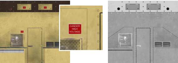
Below are examples of hi-res textures assigned to the first pass of the DD40 interior front. Generally match the ratio of physical model dimensions to the texture. This way we eliminate details being stretched when mapping.
It is fairly important to limit the highlight and shadow variations to the hires diffuse textures as this will be created by 3dsmax during the render phase. Adding dirt and subtle surface texture is usually necessary (keep detail and texture consistent over all hires textures).
In many cases we will also create and assign greyscale bump maps to add additional surface variation and relief.
You can alter the material properties by altering the `specular' and `glossiness' settings before the next texture pass of rendering.
| Hi-res diffuse map (800h x 887w) for the DD40 cab | Hi-res bump map (800h x 887w) for the DD40 cab |
Phase 4 - Lighting Placement
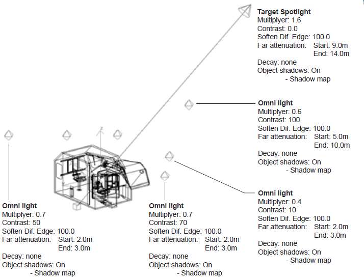
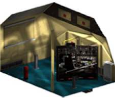
Once the first texture pass is finished it is now time to strategically add lighting to the scene. 3D Studio Max ships with a variety of light types.
The ones we generally use are the following:
 |  |
Phase 5 - Rendering for Real-time
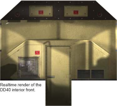
The next step is to the second texture pass. This involves rendering all details and surfaces (front, back, sides, floor, ceiling, door recesses etc.).
There is a very handy 3dsmax material plugin called "Cast Shadows Only" from Blur Studios This material makes the object invisible, but lets it cast shadows. Very handy when trying to control what does and doesn't render in a scene.
We create another cab shell with the window cut-outs to completely surround the textured cab shell. This casts the window shadows over the model.
Download the 'Cast Shadows Only' plugin for 3dsmax4 from this webpage: http://max3d.3dluvr.com/plugins.php This plugin requires a utility called 'blurlib' available on the same site. You may need to use the search box on the site to locate the files.
Phase 6 - Real-time Textures and Placement
This Phase takes all the rendered out textures (from Phase 5) and manipulate them into a format that TRS can read.
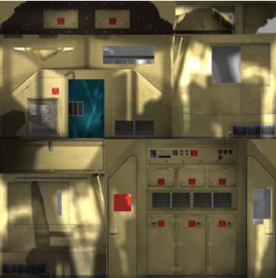
The following example is one of the real-time textures from the DD40 interior. Note the front render described before is now part of the real-time texture. As are the two sides and the rear render.
The front door however has been rotated 90 degrees and the floor render is in its place. This is in order to economically utilise the texture space.
Once the render manipulation is complete, you will probably have to re-assign much of the new textures back onto the model. In many cases this should just consist of re-doing the Unwrap UVW command.
Phase 7 - Real-time Model Spit-up and Attachments
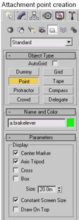
After all your real-time textures have been mapped, it is now time to split up the model into logical divisions and add attachment points. Doing this in the logical order described below will save a lot of time and frustration.
Remember to save a non-split version for backup!
Any object in the scene that has to move (ie. levers and dials), or animate, will need to be `detached' from the main model. To do this, select the polygons or elements you want detached and through the 3dsmax modify panel, press the detach button and name the new object.
To make life a heck of a lot easier later on, it pays to move the pivot point of each new object to it's logical position. Ie. For needles and levers the pivot point should be the centre of rotation (with the rotation around the Z axis). Align lever shaft in the Positive Y direction.
To do this, access the 3dsmax Hierarchy panel, and press Affect Pivot Only. From here you can centre and align the pivot to the object and move it to the preferred location.
Note: GMax users It is of course possible to skip Phase 3 to 6 and create the real-time textures yourselves with a 2d editing program such as Photoshop or Paint Shop Pro before assigning them to the model.
Study the cab interiors that Auran has included in Trainz as correct lighting variations truly add to the 3D feel of the interior.
Studying how light falls on and reflects off different materials and adding this knowledge to your textures could be the difference between a nice cab and an awesome one.
3DSMax does remove a lot of the guesswork and has the ability to create flowing, seemingly natural lit scenes. It might take a little extra time but the results are worth it! Rendering options are not available in GMax.
These attachments are exported as part of the default mesh (or the main mesh). Objects for attachment must not be included in the export as they are each exported from their own 3DSMax files and attached to the default mesh separately (through config.txt reference).
Save a backup of the 3dsmax file!!
Select each object from the scene and save each one as its own 3dsmax file, (command panel, file - save selected). You may delete the object from the main mesh scene after you save it.
The next step is to open each 3DSMax file you have just created (of the movable objects), and move the object to 0,0,0
and make the rotational values 0,0,0 (press and right click these 3dsmax icons). This makes the object (and it's pivot) aligned correctly to the origin of the scene.
Now is the time to export the object to a Trainz mesh file (.im).
Note: When a lever is inserted into the default mesh it is attached at the lever's origin, regardless of the geometry the lever has. Setting the pivot point of the object earlier, and aligning the object to the origin in it's own scene, reduces the possibility of alignment errors.
The rotation is always through the attachment point's Z axis and the in-game notch display defaults from the positive location (clockwise) around the Z axis. Altering the angle settings in the config can adjust the notch position.
Refer to the config.txt example earlier
Phase 8 - Exporting an Config.txt File Setup
Exporting the objects is very simple. You will need the Trainz Exporter Plugin for 3DSMax, GMax (or Blender)
The latest versions of the exporters are available from here
or the GMax Asset Creation Studio,
http://www.auran.com/trainz/creation/Trainz_Asset_Creation_Studio.zip
Select the objects within the scene that you want exported, from the command panel, press File, Export Selected, select Trainz Format and remember to type in the file extension in the File name dialogue box.
All mesh files should be within the same directory as the config (or in a directory within the same path). The config.txt may contain a sub-path to find the mesh, e.g.
When exporting the default mesh, you must include all attachment points. TRS may crash if the config.txt references an attachment that is not there.
Config.txt file set-up
There are a few key things to remember.
1. Mesh-table:
- An interior uses the same properties as any TRS mesh-table, you need to add auto-create 1 or the mesh will not show in the scene. There may be occasions where you don't want a mesh visible by default. Take the switchlights for example. These have auto-create 0 in the config as their visibility is controlled by script when the switch is in the on position.
2. Animations:
- Note the animated fan and the wipers do not have the animation-loop-speed tag added. This is because the animations are controlled through the script. They are visible by default, but the animation does not play by default.
- Should we have added animation-loop-speed 1 the looping animation would have played by default (with or without a script)
3. Levers:
- The visors, swivel chair and sliding windows are all setup as levers. In these three cases the notchheights are 0 so they don't display.
- In the case of the visor and sliding windows, they each have a number of invisible notches. This is to give the user the option to have them 'slightly' open or 'partially' closed.
- The sliding windows have a very large radius (30m), and very small angles.
Previous Page . . . . Next Page
